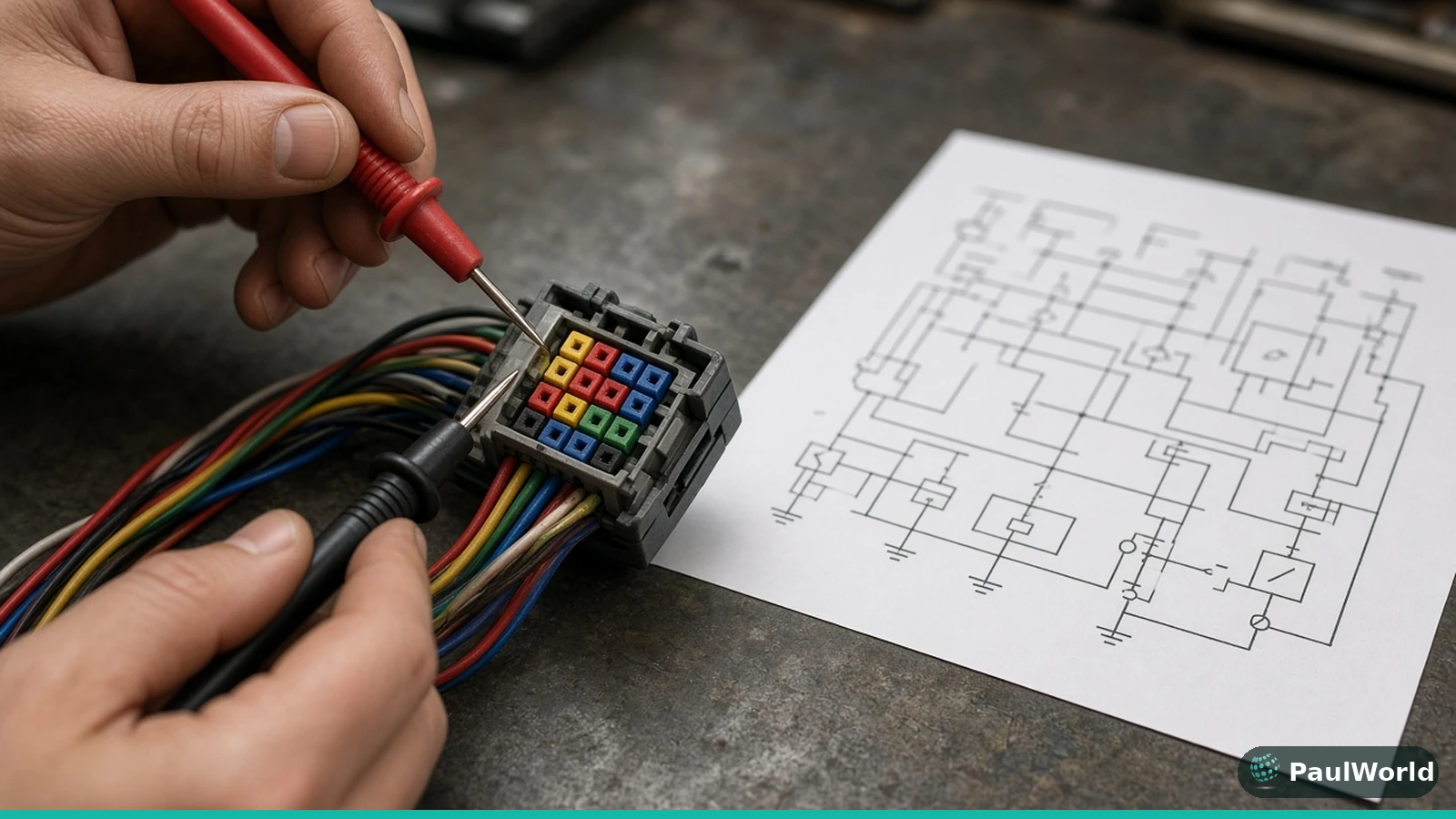
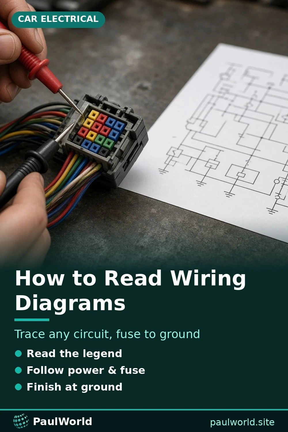
To read an automotive wiring diagram, start with the legend to learn its symbols and wire color codes, find the component you are working on, then trace the circuit in the order current flows: from the power source and fuse, through switches, relays, and connectors, to the load (the part that does the work), and finally to ground. Once you can follow one complete circuit from fuse to ground, you can use the diagram to find exactly where to test with a multimeter.
This guide explains the common symbols, how wire colors and connector numbers are shown, and a step-by-step method for tracing any circuit.
Wiring Diagram vs. Schematic: What You Are Looking At
People use the terms loosely, but there is a useful difference:
- Schematic (electrical diagram): shows how components are connected electrically, arranged logically from power at the top to ground at the bottom. It does not show where parts sit in the car.
- Component location and harness diagrams: show where connectors, grounds, and splices are physically located on the vehicle.
- Connector views (pinouts): show the face of each connector and which wire goes to which terminal.
Most factory service information uses all three together. The schematic tells you what to test, and the location diagrams tell you where to find it.
Common Automotive Wiring Diagram Symbols
| Symbol | What it usually looks like | What it means |
|---|---|---|
| Wire | A solid line | A conductor carrying current |
| Splice | A dot where lines join | Two or more wires joined together |
| Crossing wires | Lines crossing with no dot | Not connected |
| Battery | Alternating long and short parallel lines | Power source (long line is positive) |
| Fuse | A wavy or S-shaped line, or a small box, between two points | Circuit protection |
| Ground | A line ending in stacked horizontal lines | Return path to the battery negative |
| Switch | A break in the line with a pivoting arm | Opens or closes the circuit |
| Relay | A box with a coil and a switch inside | A small current controls a larger one |
| Motor | A circle with an M | Electric motor (fan, window, pump) |
| Bulb | A circle with a loop or X inside | Light |
| Resistor | A zigzag line or a rectangle | Limits current |
| Diode | A triangle pointing at a bar | Allows current one way only |
Symbols vary between manufacturers, so always check the legend in the service manual you are using.
How to Read Wire Color Codes
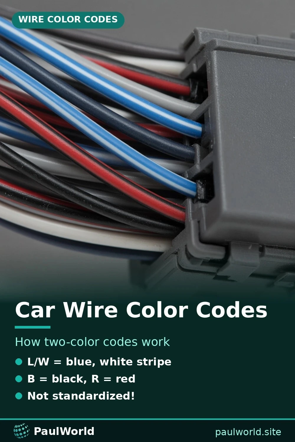
Wire colors are usually written as abbreviations next to each line. A two-part code means a base color with a stripe: the first color is the insulation and the second is the stripe. For example, in many Asian manufacturers’ manuals, L/W or L-W means a blue wire with a white stripe. Common abbreviations include:
- B or BK = black, W or WH = white, R or RD = red, G or GN = green
- L or BU = blue (L is common in Japanese manuals), Y or YE = yellow
- BR = brown, GY or GR = gray, O or OG = orange, P or PK = pink
- LG = light green, V or VT = violet
Some German manuals use German abbreviations, such as SW for black and RT or RO for red. There is no universal rule for which colors are power or ground, so never assume a red wire is power or a black wire is ground. Read the diagram.
Understanding Connectors, Terminals, and Splices
Connectors are labeled with an ID (for example, C201) and each cavity has a terminal number. Diagrams also note whether the connector face is shown from the terminal side or the harness (wire) side, which matters because the pin layout is mirrored between the two. Splices often carry IDs such as S100, and grounds may be numbered (such as G101) so you can locate them on the component location pages.
Switches are drawn in their normal resting position, typically with the ignition off, doors closed, and pedals released, unless the legend says otherwise.
How to Trace a Circuit Step by Step
- Identify the system and component. Find the correct diagram for your exact year, model, engine, and options.
- Find the power source. Note whether the circuit has power at all times (“hot at all times”), only with the ignition on, or only in run/start.
- Locate the fuse. Write down its number, rating, and which fuse box it is in.
- Follow the wire through controls. Note each switch, relay, connector, and splice in order, along with wire colors and terminal numbers.
- Reach the load. This is the motor, bulb, sensor, or module that does the work.
- Follow the ground. Trace the wire from the load to its ground point and note where that ground is on the body or engine.
- Mark your test points. Choose places along the path where you can check for voltage or voltage drop.
Example: A Simple Horn Circuit
In a typical horn circuit, battery power goes through a fuse to the horn relay’s switch side. Pressing the horn button completes the relay’s control circuit, often by providing a ground path through the steering column. The relay closes, sending power to the horns, which are grounded to the body. If the horn is dead, the diagram shows you where to test: fuse, relay power, relay control, horn power, and horn ground.
Using the Diagram With a Multimeter
A diagram becomes powerful when you pair it with a digital multimeter. With the circuit powered and switched on, check for voltage at each point along the path, starting near the load and working back toward the fuse. Where the voltage disappears, the fault lies between that point and the last good reading. Checking voltage drop across a ground connection while the circuit is working is one of the fastest ways to find a bad ground. For resistance or continuity checks, always disconnect power first.
Avoid probing airbag circuits and high-voltage hybrid or EV wiring (often orange cables). Those systems need professional procedures.
Where to Find Wiring Diagrams for Your Car
- Factory service information from the manufacturer (often available by subscription)
- Professional repair databases, sometimes accessible free through public libraries
- Printed or online repair manuals for your model
Make sure the diagram matches your exact vehicle, because the same model can have different wiring by year, engine, and trim.
Read the Legend and the Operating State First
Before you trace a single wire, check two things on the diagram’s first page.
- The legend: Manufacturers use different symbols and color abbreviations. Never assume a convention from one brand applies to another.
- The operating state: Diagrams are usually drawn “at rest,” with the ignition off. Test notes may refer to states such as KOEO (key on, engine off) or KOER (key on, engine running). If you test in the wrong state, a healthy circuit can look faulty.
Most manufacturer diagrams also flow from power at the top of the page to ground at the bottom, which gives you a natural reading direction.
Relay Circuits: Trace the Control Side and the Load Side Separately
Many circuits, including horns, fuel pumps, and cooling fans, use a relay. A relay is really two circuits in one:
| Side | What it does | Typical path |
|---|---|---|
| Control side | A small current energizes the relay coil | Fuse → switch or module → relay coil → ground |
| Load side | The relay contacts carry the working current | Fuse → relay contacts → load (horn, fan, pump) → ground |
The load can have perfect power and ground while the control signal is missing, or the reverse. Checking each side on its own prevents guesswork.
Pro tip: Many relays are interchangeable with a nearby relay of the same part number. Swapping them is a quick, free test. Check that the part numbers match first.
Turn the Diagram Into a Test Plan
Before you probe anything, write down each test point with four details:
- Condition: What must be on, connected, or commanded?
- Location: Which connector and which pin (cavity)?
- Expected result: Battery voltage, ground, or a signal?
- Next step: If it passes, where do you test next? If it fails, which way do you move?
Expected values should come from the service information for your vehicle, not from memory.
Why Voltage Drop Beats a Continuity Test
A wire can pass a continuity test with just one surviving strand, yet fail the moment it carries real current. A voltage-drop test is done with the circuit operating: you measure across a section of wire, connector, or ground while the load is on. A reading above the specification points to resistance hiding in that section.
Common mistake: Ignoring continuation arrows and page references. Multi-page diagrams continue a wire on another page. Skipping one can make a circuit look like it ends where it does not.
Common mistake: Back-probing too aggressively. Forcing a large probe into a connector cavity can spread the terminal and create a new intermittent fault. Use proper back-probe pins.
Frequently Asked Questions
What does a dot mean on a wiring diagram?
A dot where lines meet usually means a splice, where wires are joined. Lines that cross without a dot are not connected.
How do you read a two-color wire code like L/W?
The first letter is the base insulation color and the second is the stripe. In many manuals, L/W means a blue wire with a white stripe.
Are automotive wire colors standardized?
No. Each manufacturer uses its own color scheme and abbreviations, and colors can change between models and years. Always use the diagram for your specific vehicle.
Why are switches shown open on a diagram?
Diagrams show switches in their normal resting state, usually with the ignition off, doors closed, and pedals released, so you can see how the circuit behaves when each switch changes position.
What does KOEO mean on a wiring diagram or test procedure?
KOEO means key on, engine off: the ignition is switched on but the engine is not running. KOER means key on, engine running. Test procedures specify the state because voltages change between them.
Do wiring diagrams show where wires are located in the car?
No. A wiring diagram shows how components are connected electrically, not their physical location or wire length. Use the component location views in the service information to find parts and connectors on the car.
Bottom Line
Reading automotive wiring diagrams comes down to learning the symbols, decoding wire colors and connector numbers, and tracing each circuit from power to ground. Practice on a simple circuit like the horn or a lamp, and electrical problems will stop being guesswork. For the bigger picture, see how cars work and our diagnosis-first guide on how to fix a car yourself. Strong electrical skills are also a big advantage if you plan to become a mechanic.
Categories
Tags